
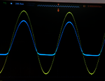
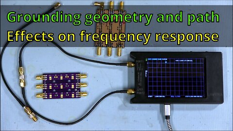
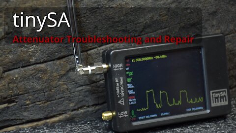
Measuring PCB trace frequency response anomaly with a VNA (#014)
Measuring PCB trace frequency response anomaly with a nanoVNA - LiteVNA. Showing effects of ground connections to an SMA RF connector.
266
views
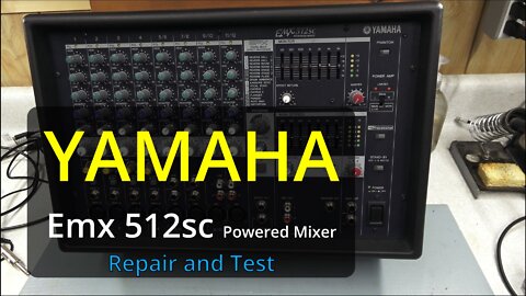
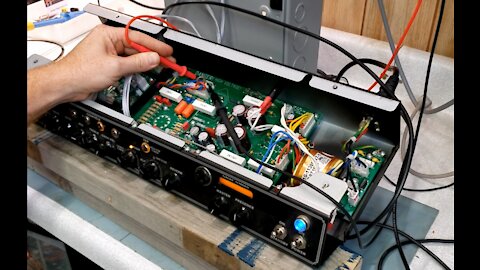
Yamaha Powered Mixer - EMX512sc - Repair and Test (#013)
Yamaha Powered Mixer - EMX512sc - Repair and Test
Troubleshooting, Reviewing schematic, Frequency response, THD and Power test.
--------------------
TIMESTAMPS:
0:00 - Intro
0:15 - Schematic
4:26 - Power supply PCB
7:14 - Frequency Response test setup
11:58 - Frequency Response CH A 100W sweep
12:36 - Frequency Response CH B 100W sweep
12:55 - Frequency Response results
13:16 - Total Harmonic Distortion test setup
13:58 - THD of channel A output
14:58 - THD of channel B output
15:14 - THD results review
15:46 - Max power test 1kHz into a 4 ohm load
16:50 - Output noise check on oscilloscope
17:19 - Real test of system
18:08 - Outro slide show and music
316
views
1
comment
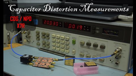
Capacitor Distortion Measurements In Audio Circuits (#012)
Capacitor distortion measurements comparing C0G/NP0 and X7R ceramic capacitors.
155
views

tinySA vs Rubidium 10MHz Frequency Standard (#011)
Comparing two tinySA, an Agilent 33120A, HP 8660D 10MHz output and calibration signal to a FE-5680A Rubidium Frequency Standard. Using an Advantest R3463 with its 10MHz reference calibrated by the Rubidium Standard.to make the frequency measurements.
Time Stamps:
0:10 - Overview
1:07 - FE-5680A Rubidium Frequency Standard.
2:00 - Advantest R3463 10MHz Reference initial check.
2:31 - tinySA 10MHz frequency comparison to Rubidium.
3:07 - HP 8660D Signal generator frequency check.
3:45 - Advantest Counter zeroing to Rubidium Standard.
5:51 - tinySA - Frequency measurement using 'aligned' counter.
7:00 - Agilent 33120A Frequency measurement.
9:06 - tinySA Output signal and cal signal setup.
9:33 - tinySA Calibration output 10MHz scope view.
10:06 - Outro - Electronics photography and acoustic guitar
384
views
1
comment
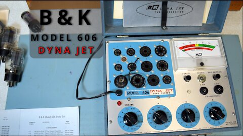
Tube Tester B&K Model 606 DYNA JET Demo (#009)
Demonstration of a B&K Model 606 Dyna Jet tube tester. Testing good and bad tubes.
137
views
1
comment
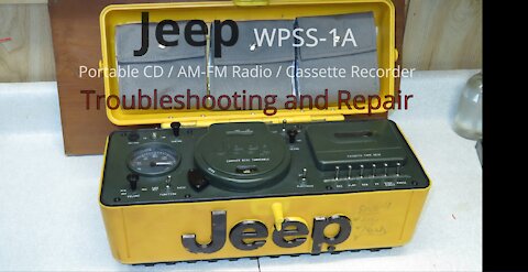
Jeep Portable CD / AM-FM Radio / Cassette Recorder WPSS-1A Repair (#008)
Repairing a Jeep Portable CD / AM-FM Radio / Cassette Recorder Model WPSS-1A.
153
views
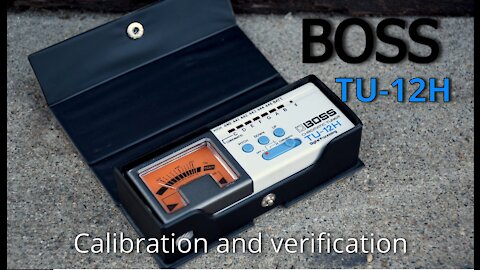
Boss TU-12H Tuner Calibration (#007)
Calibration and verification of a Boss TU-12H chromatic tuner. The needle was slightly off. Simple internal adjustment and using a stable reference signal allows re-centering the needle.
238
views
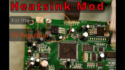
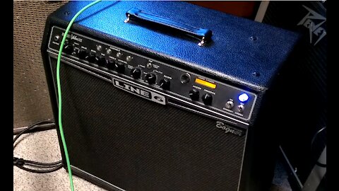
Line 6 Spider Valve 112 - Custom 5V Regulator Heat Sink (#006)
Adding an additional heat sink to the 5V regulator reducing the component temp by about 50ºF. Before and after temperature measurement using a thermal imaging camera and cheap handheld IR thermometer.
103
views
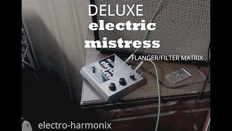
electro-harmonix Deluxe electric mistress flanger Troubleshooting and Repair (#005)
Troubleshooting and repair of an Electro-Harmonix Deluxe Electric Mistress Flanger guitar effects pedal.
252
views
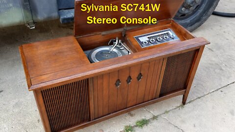
Sylvania SC741 Stereo Console - Repair and Refinish (#004)
Troubleshooting and repair of a Sylvania SC741W Stereo console.
290
views
3
comments
Tube Amp Bias - Default vs MinTHD and Bode plot on the Line 6 Spider Valve 112 (#003)
An experiment in biasing a tube amp.
Comparing 2 methods:
1. The recommended default bias of 35mV (=35mA)
2. Biasing for minimum % THD at 1kHz.
Additionally showing the amplitude vs frequency response of both methods.
Finally and audio comparison of the 2 bias methods.
116
views
Line 6 Spider Valve 112 - Troubleshooting and Repair (#002)
Troubleshooting and repair of a Line 6 Spider Valve 112.
Symptoms:
No sound when using the front input jack.
No LED indicators working on front panel.
LCD display not working.
918
views
14
comments
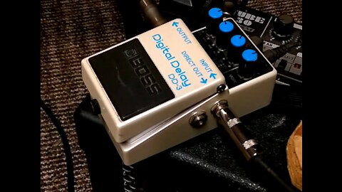
Boss DD-3 Delay Pedal - Troubleshooting and Repair (#001)
Troubleshooting and repairing a Boss DD-3 Delay Pedal. This is an earlier version which appears to share the same schematic as the DD-2 and has all through-hole components.
Symptom: No sound at the main output.
Clarification: The 400mV note at 1:56 is peak to peak voltage.
524
views

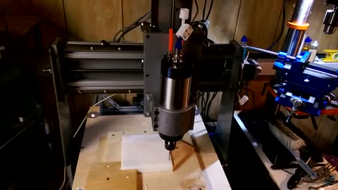
CNC aluminum with simple G code -early testing
Early testing of my CNC machine on aluminum to document progress. I just wrote a short G code file to make the simple moves show to see if the machine would lose steps or have any other issues cutting aluminum. There are all sorts of stepper motor settings which combined with power supply voltage and gearing affect performance and movement rates.
Setup:
1. Unknown CNC machine (old) kit.
2. New spindle motor and controller.
3. Tiny G V8 pcb with on-board motor controllers.
4. Chilipeppr control software: https://github.com/synthetos/TinyG/wiki/Chilipeppr.
Result: Success. No lost steps or broken parts.
98
views
3
comments
CNC - simple G code drill operation into soft plastic
This video shows a basic drill operation using a few lines of G code.
The spindle was manually adjusted into position using Chilipeppr software before starting the operation.
I found it fairly quick to program just automate 1 drill operation then go the the next location and stop. If nothing went wrong, just click the run button again to start the next hole..
Here is G-code with additional spindle automation and lots of comments:
(Drill holes and go to next position to prepare for next hole.)
(Drill bit size #23, 20-55 RPM. Soft plastic)
(Only drill ? holes at a time to allow clearing of shavings)
(Set bit about 1/4" above work piece)
G20
M03 (SPINDLE ON clockwise)
G04 P5.0(Wait for spindle to ramp up)
G91 G01 F20 Z-0.50 (Drill hole - G91 is incremental mode, G01=move at feedrate F, G00 is move at max rate)
G91 G00 Z0.50 (raise drill out of material)
G91 G00 X1.00 (Go to hole 2 location 1" on x axis)
(repeat as needed for more holes)
(End of drilling)
M05 (stop spindle)
M02 (end program)
86
views
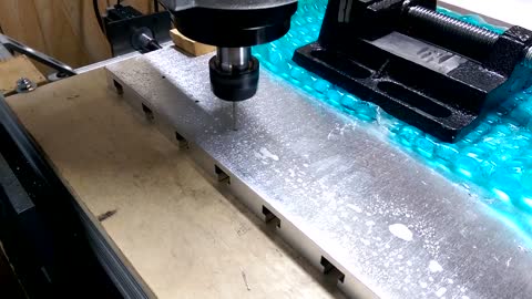
CNC drilling holes for new aluminum T-Slot bed
Drilling holes on my new aluminum T-Slot bed to prepare for mounting it. Used Peck drilling to prevent drill shaving issues, but am not sure if it was necessary at this depth.
Here is the G-code (numbers are in inches):
G20
(Start with bit .5" above 1st hole location at back left)
M03 (SPINDLE ON clockwise)
G04 P5.0(Wait for spindle to ramp up)
G91 (relative position)
(Start Hole 1)
G01 F20 Z-0.8 (peck 1)
G00 Z0.8
G01 F20 Z-1.1 (peck 2)
G00 Z1.1
(Start Hole 2)
G00 Y -2
G01 F20 Z-0.8 (peck 1)
G00 Z0.8
G01 F20 Z-1.1 (peck 2)
G00 Z1.1
(Start Hole 3)
G00 Y -2
G01 F20 Z-0.8 (peck 1)
G00 Z0.8
G01 F20 Z-1.1 (peck 2)
G00 Z1.1
(Start Hole 4)
G00 Y -2
G01 F20 Z-0.8 (peck 1)
G00 Z0.8
G01 F20 Z-1.1 (peck 2)
G00 Z1.1
(Start Hole 5)
G00 Y -2
G01 F20 Z-0.8 (peck 1)
G00 Z0.8
G01 F20 Z-1.1 (peck 2)
G00 Z1.1
(Start Hole 6)
G00 Y -2
G01 F20 Z-0.8 (peck 1)
G00 Z0.8
G01 F20 Z-1.1 (peck 2)
G00 Z1.1
(Start Hole 6)
G00 Y -2
G01 F20 Z-0.8 (peck 1)
G00 Z0.8
G01 F20 Z-1.1 (peck 2)
G00 Z1.1
M05 (stop spindle)
(Return Home)
G00 Y 12
M02 (stop program)
51
views