

What Do Those Code Terms Mean? NEC Codebook
The NEC is the book we, as electricians, use as a guideline to install our work. It tells us the minimums and maximums for the applications. But the code can be confusing at times, especially if you are new to the trade. In this latest episode of Electrician U, and part 3 of the Confusing Code Terms series, Dustin explains a few of the terms within the codebook to bring some light (pun intended) to the topics!
🤘⚡️MEMBERSHIP⚡️🤘
JOIN ELECTRICIAN U - become a member and get:
FREE Continuing Education every year
FREE Practice Exams
FREE Monthly Video Courses
FREE Monthly Educational Newsletter
Premium Members-Only Content
Private Discord Channel
Monthly Members-Only Discord Chats
Sign up here --- https://www.electricianu.com/electrician-u-membership/
🎧🎹MUSIC AND VIDEO:🎹🎧
https://www.facebook.com/descantmv
🎬✍️ART AND ILLUSTRATION:✍️🎬
https://www.daverussoart.com
Overcurrent Protection Device (OCPD) is simply a device that provides equipment with protection from the damages of too much current (amperage). The two most recognizable being breakers and fuses. When a breaker senses that there is more current on the circuit than it is rated for, the contacts open and the current ceases to flow to the equipment. For a fuse, when more current is flowing through the fuse than it is rated for, the fuse blows, the circuit to the equipment becomes open, and current flow stops.
Overvoltage Protection is just that; it provides a piece of equipment protection from the damaging effects of having too much voltage applied to it. Surge protectors are what comes to mind when we talk about overvoltage protection. When the device senses too much current flow through it, just like a breaker, it opens the circuit creating a buffer between the offending voltage and device plugged into it. Damaging surges can happen within the specific electrical system itself or they can happen from the utility side. Note, surge protection should NOT be confused with lightning protection as that is something completely different!
Tamper Resistant Receptacles are next. This is a standard receptacle with a set of “shutters” in the holes where the blades of a plug would go that allow the plug to be inserted but disallow something that shouldn’t be in there (like a knife, scissors, etc.) to be inserted. This keeps small children from putting something into a receptacle and getting a nasty shock. Most places where a child could be left unattended/monitored are generally required to have these devices installed. These include, but are not limited to, doctors offices, public waiting areas, and even houses!
What exactly is a wireway? A wireway should not be confused with pipe or conduit. Pipe is something that traditionally has a pressurized something in it (water, hydraulics, etc.) and conduit is round tubing that an electrician pulls wire into. A wireway is usually a trough that we install wire in, like a gutter in between pieces of equipment or on the end of conduit runs. They are also equipped with removable covers so that the wires contained within can be accessed. Article 376 covers metallic wireways, while Article 378 covers nonmetallic wireways. The actual definition of those wireways is in their respective code articles at the beginning (this is typical of many code articles).
Appliances, equipment, and devices are 3 separate terms but go together. The NEC defines equipment as a general term- as a part of, or in connection with, an electrical installation. In simpler terms, anything tied to an electrical installation. Couplings, connectors, boxes, straps, etc. fall into this category. An appliance is a piece of utilization equipment that is built in standardized sizes/types and installed/connected to perform a function (like a clothes washer or air conditioner). To make it easier to understand, think of something that is manufactured and you bring IN to the installation. A device is a unit of an electrical system (other than a conductor) that carries or controls electric energy. In essence, something that brings electricity to a point that you can USE that electricity to operate your APPLIANCE or EQUIPMENT.
We hope this answers some of the questions you had! Please continue to follow Electrician U and Dustin as we are constantly adding new content to assist our followers!!
#electrician #electrical #electricity
90
views

Five Essential Hand Tools Apprentice Electricians Need!
As electricians, we need tools in our hands to perform most of the tasks that we do. Over the course of an electrician’s career, most of us end up with a staggering number of tools! We just need a lot of tools to perform our jobs. But with almost an infinite number of tools available to us, which are the tools that we need the most? While most of the tools in an electrician’s arsenal are multi-purpose, some of our tasks require specific tools to accomplish. In the latest episode of Electrician U, Dustin gives some explanation to 5 hand tools that are essential to an electrical apprentice.
SPONSOR: Milwaukee Grid ⚡️ https://www.milwaukeetool.com/Grid
🤘⚡️MEMBERSHIP⚡️🤘
JOIN ELECTRICIAN U - become a member and get:
FREE Continuing Education every year
FREE Practice Exams
FREE Monthly Video Courses
FREE Monthly Educational Newsletter
Premium Members-Only Content
Private Discord Channel
Monthly Members-Only Discord Chats
Sign up here --- https://www.electricianu.com/electrician-u-membership/
🎧🎹MUSIC AND VIDEO:🎹🎧
https://www.facebook.com/descantmv
🎬✍️ART AND ILLUSTRATION:✍️🎬
https://www.daverussoart.com
The first tool to consider are lineman’s pliers. This is the electricians multi-purpose tool, and usually the tool we tend to grab first. They can cut wire (among many other items!) and have knurled jaws to grab onto items like bolts, screws, wire etc. They have long handles that provide extra leverage and have considerable heft to them to assist the electrician. Lineman’s pliers also come with a variety of options from crimpers to fish tape pullers, even spring-loaded jaws. A definite must have!
Needle nose pliers are also essential to the electrician. While closely resembling lineman’s pliers, they are smaller in size, and the head is tapered to a point on the end. We use them to loop wires around the screws of devices, cut wires, and grab smaller items. Needle nose pliers allow us to reach into smaller more crowded areas like junction/device boxes. They come with several options on them from wire crimpers, to screw cutters, even stripping holes if you needed to strip a wire without having to swap tools. Another essential tool for us electricians!
Diagonal cutting pliers are the next tool on our list. This tool again resembles a pair of lineman’s pliers but lack the part of the tool used to grab onto things. This tool is generally meant to cut only. While we normally use them to cut copper wire, they can also be used to cut aluminum, mild steel, or anything non hardened. In addition, they tend to be handy when prying smaller items like nails or staples. You can get them in several different sizes as well as flush cutting for the finer work (or cutting tie wraps flush). A pair of these pliers are a must for the electrician!
A good pair of wire strippers are a necessity for electricians to have. Wires tend to not be as effective without exposing the copper (or aluminum) on the ends to terminate to a device! Wire strippers come in a variety of sizes, with some being for smaller conductors and some being able to strip and cut larger conductors we use, and have several holes allowing us to strip a range of wires. They can also be used on either solid or stranded wires and do have a small set of jaws on the leading edge to grab onto things or bend a loop in a wire. This tool also has options available like crimpers or screw cutters to trim down device screws during installation. Different physical sizes are available to fit most hand sizes and ergonomic versions are also out there to help combat hand fatigue from hours of constant use.
The last tool is an electrician’s tool. This type of tool is a variation/combination of some of the tools above. Not specifically like any one of them, but rather a mash up of all of them. They are smaller than lineman’s pliers, but still have some heft to them. They have stripping holes in them to strip wires and have a snout on the end that allows you to twist wires together or grab items. These are great for carrying to a task if you do not want to carry ALL the other tools mentioned above. A multipurpose tool that is good for general use.
We hope this has been insightful and helpful to determine what tools are essential to an apprentice. Please continue to follow Dustin and Electrician U as we are constantly adding new content to improve our followers’ careers!
187
views

What is the Difference Between Single Phase and Three Phase???
Single phase power and 3 phase power are terms we hear quite frequently in the electrical world. But what are the differences between them? In the latest episode of Electrician U, Dustin explains the differences and benefits to each in a never-ending pursuit to answer our followers’ questions.
Check Out Legrand
https://www.legrand.us/wiremold/rfba-floor-boxes
🤘⚡️MEMBERSHIP⚡️🤘
JOIN ELECTRICIAN U - become a member and get:
FREE Continuing Education every year
FREE Practice Exams
FREE Monthly Video Courses
FREE Monthly Educational Newsletter
Premium Members-Only Content
Private Discord Channel
Monthly Members-Only Discord Chats
Sign up here --- https://www.electricianu.com/electrician-u-membership/
🎧🎹MUSIC AND VIDEO:🎹🎧
https://www.facebook.com/descantmv
🎬✍️ART AND ILLUSTRATION:✍️🎬
https://www.daverussoart.com
Let’s start off by defining them. Single phase is referring to a single loop of current flow. One big loop! One can also think of single phase as two hots (typically A and B phase or Black and Red). Current is flowing TO the load on one wire (say the black wire) and returning TO the source on the other wire (say the red wire). They are also alternating back and forth between pulling and pushing the current flow. Try to conceptualize the sine wave chart. As one of the conductors is pushing the current (black), the other is pulling (red). Until they both get to the neutral (or zero point) where it begins to go the other way. Black will pull and red will push.
Three-phase on the other hand is referring to 3 loops of current flow from 3 separate generating sources. Same type of general concept except that they are tied together. As before with single phase, current left on the black, travelled thru the load, and returned on the red. Here in three phase, current leaves on the black, travels thru the load, and returns on the red. However, that red ALSO happens to be powering the one side of its own generator as well that will leave on its red conductor and return on another conductor (blue). This blue is ALSO tied to ITS own generator that current will leave on the blue, travel thru the load, and return on the black, and we start the sequence all over again! So, they are all separate loops but tied together to form another loop so they can share the load amongst themselves.
The terms Primary and Secondary also come into play here. Primary refers to the conductors on the side Feeding the transformer, Secondary refers to the conductors on the other side that will be utilized by us. Transformers operate by induction. When we push/pull current thru the transformer on the primary side of the coil, it induces movement of current on the other secondary coil (transformers have coils that are close to one another but not touching) and that current flow is what provides us the stepped down power we need.
One of the big reasons WHY we would use 3-phase for some applications is due to efficiency. Remember our sine wave chart? On single phase, work is being done when the points are at their farthest distances apart from one another. But when they both come back to the zero point (at the same time, remember), there is no work being done at all as they are both at zero. On a 3-phase system, when one of the 3 phases is doing ALL the pushing, the pulling action on the other end is being shared equally by the other 2 phases. And that alternates between all three of the sets. So, on a sine wave chart, when one conductor is at its highest point, the other two are not exactly opposite of it because they are sharing the work. And, then THEY alternate also. So, at no point is anything sitting idle on a three phase, thus more efficient for larger scale type items like factories, plants, warehouses, etc.
We can also get motors in either single phase or three-phase. Same type of concept and for the same reasons. Efficiency! The three-phase motors share the work among the three points of power.
We hope this answers the age old question of the differences between single phase and three phase. Please continue to follow Dustin and Electrician U as we are constantly adding new content to bring clarity to the electrical trade!
#electrician #electrical #electricity #
80
views

How To Install a Ring Video Doorbell Wired - From an Electrician
In this day and age where there are so many home security products available to us, as well as the option to install these things ourselves, how does it work? In the latest episode, Dustin takes us through the steps of installing a Ring Doorbell to an existing wired doorbell system.
🤘⚡️MEMBERSHIP⚡️🤘
JOIN ELECTRICIAN U - become a member and get:
FREE Continuing Education every year
FREE Practice Exams
FREE Monthly Video Courses
FREE Monthly Educational Newsletter
Premium Members-Only Content
Private Discord Channel
Monthly Members-Only Discord Chats
Sign up here --- https://www.electricianu.com/electrician-u-membership/
🎧🎹MUSIC AND VIDEO:🎹🎧
https://www.facebook.com/descantmv
🎬✍️ART AND ILLUSTRATION:✍️🎬
https://www.daverussoart.com
As with installing anything, until you get well used to handling any particular item (and even then, after or when changing manufacturers) READ THE DIRECTIONS!! Most of us men tend to miss this part, but it is an important step that should be taken! Second thing to do is TURN OFF THE POWER. Last thing we want to do is get shocked! Also, since we are dealing with sensitive electronics, the power should be shut off, so we don’t burn anything up on the low voltage end.
There are 3 general components to a doorbell system. The doorbell button, the transformer, and the chime. With the power off, remove the existing button on the wall at the door. Be super careful as the 2 wires at the button itself tend to be cut rather short, and we don’t want them falling back into the wall so we cannot use them! Once the button is removed, install the new mounting plate over the existing hole in the wall making sure to cover all the old surface area so there is no painting involved. Also, if you are using the angled back plate to kick the new camera away from the door itself, install the screws at a slight angle so they end up flush with the plate. Next, re-terminate the existing wires onto the screws of the new button, one wire per screw, and ensure that the wires aren’t shorted together. Don’t over tighten the screws but do make sure they are tight. Next item is to fasten the camera itself to the backplate with the provided screws. When you install the device, you want the camera at the top and button at the bottom, otherwise your image will be upside down. Once you have the camera mounted the last thing needed is to snap the cover onto the camera and use the provided screw to fasten the cover to the camera. This screw is usually on the bottom and will probably be a non-standard type head (not a Phillips or straight) so it cannot be easily removed.
Once the button installation sequence is completed, the next item to be done is to install the camera power pack to the existing doorbell chime. When you install the power pack to the chime, you want to be sure that you are not impeding the chime portion. You will need to look at the existing chime and find a place to install the pack. Once you have wired it into the existing chime and put the chime cover back on, the power can be turned back on.
The last item to do is to follow the manufacturer's instructions on linking the new bell to the Wi-Fi and your phone. You now should be good to go and can use the new doorbell!
We hope this video was instructional and provided the information needed to install a Ring Doorbell on your own! Please continue to follow Dustin and Electrician U as we are constantly adding new content regularly.
#electrician #electrical #electricity #ringvideodoorbellwired #ringcamera #bestdoorbellcamera2022 #howtoinstallringdoorbellwired #ringdoorbell4 #ringdoorbellwiredwithringchime #howtoinstallringdoorbell #horwtoinstallringdoorbell4 #ringdoorbellpro
93
views

Tips on Keeping Cool at the Jobsite (for Electricians) (and all Trades)
Let’s face it. We don’t normally get to pick and choose the environments in which we get to perform our electrical trade. And, depending on the part of the country where you live/work, some of those areas can be brutal in the summertime when it comes to the heat. I know here in Texas, temperatures can be well over 100 degrees in the shade! In the latest episode of Electrician U, Dustin gives some tips and pointers on how you can combat the effects of working out in the heat.
🤘⚡️MEMBERSHIP⚡️🤘
JOIN ELECTRICIAN U - become a member and get:
FREE Continuing Education every year
FREE Practice Exams
FREE Monthly Video Courses
FREE Monthly Educational Newsletter
Premium Members-Only Content
Private Discord Channel
Monthly Members-Only Discord Chats
Sign up here --- https://www.electricianu.com/electrician-u-membership/
🎧🎹MUSIC AND VIDEO:🎹🎧
https://www.facebook.com/descantmv
🎬✍️ART AND ILLUSTRATION:✍️🎬
https://www.daverussoart.com
The clothing you wear can have a huge impact on how your body reacts to rising temperatures. If you were to wear shorts, T shirts, and tennis shoes, you would probably feel much more comfortable than in the full pants, shirt, and boots most of us are required to wear. But OSHA is the driving force behind what you can wear and what you cannot. In fact, they put the responsibility on the Employer to define what is safe/appropriate to wear to work. Some employers are fine with the employee wearing shorts, T shirts, and tennis shoes if they are working Inside on a smaller project (like a house for example).
If you are like most of us, pants are what we normally don to go to work. This provides a level of protection to your lower body that shorts cannot. Long sleeve shirts also offer some protection to the upper body. The things we, in the construction industry, do during the course of the day require some form of protection to our bodies. Drilling in metal/wood with shavings flying around, crawling around in attics or crawlspaces, and working with some unforgiving materials and tools to name a few. In addition, covering your body with clothing also keeps it out of the suns damaging rays. There are many different forms of fabric that offer some form of UV protection, are lightweight and breathable, have sweat wicking ability, etc., but even cotton can provide some of these benefits as well. Some form of covering on your head is also helpful.
Don’t neglect your feet when you are dressing for the warm weather. Make sure you select a good pair of work boots that suit your needs as well as the appropriate socks! While cotton socks are lightweight consider a pair of wool boot sock to help wick some of that sweat away. Your boots should be selected with the amount of physical protection you need in addition to any other items you may be looking for (ankle support for example). They should also be sturdy, and you shouldn’t have to replace them every couple of months!
Safety glasses/sunglasses are something else to consider. There are tinted safety glasses available, but at a minimum, consider wearing a pair of inexpensive sunglasses if working out in the sun. You won’t be squinting as much, and they can help keep things from getting into your eyes.
Of course, sunscreen is very helpful in keeping you from getting burned. Either the spray or lotion types are perfectly fine, and if you can find some that is sweatproof, even better! Water consumption is something that should NOT be overlooked. If you are exerting yourself, a reasonable gauge is to start at a gallon a day and go up from there. And while sports type drinks are helpful, nothing can replace good old water! Keep some in a cooler reasonably close to you in the hot months and drink that water frequently.
Many companies offer products that are self-cooling. Things like towels, do rags, hard hats, etc. These items should not be overlooked as they can be a big help in keeping you cooled down.
Make sure to check out the entire video to catch ALL the tips Dustin talks about.
#electrician #electrical #ppe
67
views
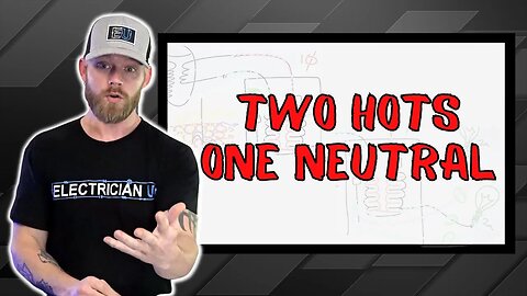
Neutral Imbalance in Multiwire Branch Circuits (Two Hots, One Neutral)
In the latest episode of Electrician U, a question came in from a viewer that needed some help understanding a topic. The question centered around sharing a neutral between 2 circuits. As this is a common practice in the construction industry, Dustin came prepared to drop some knowledge on the subject in an ongoing effort to better our viewers understanding!
🤘⚡️MEMBERSHIP⚡️🤘
JOIN ELECTRICIAN U - become a member and get:
FREE Continuing Education every year
FREE Practice Exams
FREE Monthly Video Courses
FREE Monthly Educational Newsletter
Premium Members-Only Content
Private Discord Channel
Monthly Members-Only Discord Chats
Sign up here --- https://www.electricianu.com/electrician-u-membership/
🎧🎹MUSIC AND VIDEO:🎹🎧
https://www.facebook.com/descantmv
🎬✍️ART AND ILLUSTRATION:✍️🎬
https://www.daverussoart.com
First, lets discuss Multiwire Branch Circuits. This is where we have multiple hot conductors paired with a single neutral. This installation can be in the form of Non-Metallic Cable (with a black, red, white, and grounding conductor) or even with MC Cable/standard pipe & wire method. Under normal circumstances, this is a perfectly acceptable practice, provided (among other things) that you have connected the hot conductors to TWO SEPARATE phases. One hot to A phase and the other hot to B phase for example. This way you don’t overload the neutral with return current from the same phase. Another thing that the NEC requires us to do is make sure that the breaker handles for the multiwire branch circuits have a common handle. This can be accomplished via a two (or three pole, if it is a three phase multiwire branch circuit) pole breaker OR other approved breaker handle tie. By doing this, if you shut off one breaker, you should not have any return current from any of the other circuits in the multiwire branch on the shared (or common) neutral conductor.
To make it a bit easier to understand, imagine, that while the black hot conductor if pushing the current thru the wire/load, the white conductor is pulling it thru. And if the red/white set were doing the same thing, then the current that is on the white conductor of a multiwire branch circuit would cancel it out and we wouldn’t have any issues. It would be the same, in essence, as a 240v 2 pole circuit with two hots. Now, this would only be true if the exact same load was on each circuit. Let’s say 10 amps. What would end up happening is the 12 ohms worth of resistance (120v divided by 10a = 12 ohms. Basic Ohm’s Law) would be doubled across double the voltage (12 Ohm’s + 12 Ohm’s on a 240v circuit now). The current is still able to make the complete loop from source, thru load(s) and return to source, therefore making a viable electrical circuit, and everything operates as it should.
Let’s get back to the statement of the exact same sized load being on each circuit and unpack that for a minute. We have discussed what would happen if the loads were balanced. But what if the loads were Imbalanced? Say 10a on one circuit and 15a on the other. Well, the neutral conductor (grounded conductor) would carry that imbalance of 5a back to source. This doesn’t necessarily pose any problem other than the fact that there are 5a of current flow on something other than the hot conductor. If we were to look at it from two single branch circuits (with the same amount of current on each), in lieu of a multiwire branch circuit, it would look much the same. 10a flowing out on the black wire, thru the load and returning on the white conductor, and the same with the red/white set. But the point where those neutral conductors came together (at the neutral bus bar) it would become 0a worth of current flow as they would cancel themselves out. So as an overall picture, the neutral is only carrying the unbalanced amount of current!
A big issue that can arise is when we do not use hots from different phases. Instead of each carrying 10a worth of current working in tandem (one pushing the other pulling for example) they are now both trying to push that 10a of current since they are both traveling the same way. So, while the breaker may be fine (10a worth of current on it) the neutral, at the point they came together, would have 20a worth of current on it since there was nothing to carry the other 10a away!
#electrician #electrical #electricity
99
views

What Does Available Fault Current Mean?
What does the term Available Fault Current mean? It’s not a term we hear terribly frequently in the industry unless you are having to mark the panel you are installing, or you hear about it while studying for an exam. It is not as baffling or confusing as it may sound! In this episode of Electrician U, Dustin talks about what the term stands for and how it is used.
🤘⚡️MEMBERSHIP⚡️🤘
JOIN ELECTRICIAN U - become a member and get:
FREE Continuing Education every year
FREE Practice Exams
FREE Monthly Video Courses
FREE Monthly Educational Newsletter
Premium Members-Only Content
Private Discord Channel
Monthly Members-Only Discord Chats
Sign up here --- https://www.electricianu.com/electrician-u-membership/
🎧🎹MUSIC AND VIDEO:🎹🎧
https://www.facebook.com/descantmv
🎬✍️ART AND ILLUSTRATION:✍️🎬
https://www.daverussoart.com
To describe the term Fault, we would be talking about an accidental occurrence of something. Something that isn’t meant to happen but did. A ground fault for example, is the accidental joining of an ungrounded conductor and a grounding conductor. The NEC defines Fault Current as “The current delivered at a point on the system during a short-circuit condition”. Furthermore, the NEC defines Available Fault Current as “The largest amount of current Capable of being delivered at a point on the system during a short-circuit condition”. A short circuit is when the current in a circuit attempts to take another path back to its source other than the path intended. This can be either via another hot (ungrounded) conductor or a neutral (grounded conductor), but not a ground conductor (this would be a ground fault).
So, Available Fault Current is the largest among of Current that is CAPABLE of flowing during a Short-Circuit. The biggest reason that we label the service with the Available Fault Current is due to the size of the wire. For example, a branch circuit within a building will definitely have much smaller size wire than the incoming service. This smaller wire will be able to contain MUCH less current than the service entrance conductors from utility. So, the hazard downstream in the potential of current is less than at the service where the potential for current is much greater. If you had several parallel runs of 500KCMIL conductors for each phase at the service, the amount of potential current being able to flow during a short circuit are massive compared to the amount that could flow on a set of #12 conductors. Length is something that also comes into play when factoring the amount of available fault current. The longer the length of the cable is, the more opposition to current flow (or impedance) there will be.
NEC article 110.24(A) states that service equipment (other than dwelling units) shall be marked in the field with the available fault current. It also states that it shall be durably marked (so the weather or environment doesn’t make it fade or wash off) and be documented/available so to anyone authorized to design, install, inspect, maintain, or operate the system. 110.24(B) goes on to say that if you were to modify the original system, you must update the available fault current to be accurate with the new work.
We hope this clears up the term Available Fault Current! Continue to follow Electrician U and Dustin’s travels as we are constantly adding new and updated information for our viewers!
#electrician #electrical #electricity
54
views
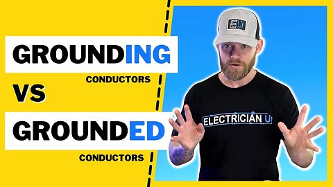
Why Are GROUNDING Conductors Smaller Than GROUNDED Conductors???
The conductors we use as electricians come in many different sizes, colors, and compositions of the metallic portion as well as the insulation portion. Most of us electricians know that the Size of the conductors we use are based upon the ampacity they will be carrying (for the most part anyway). So why then, are the “Grounding” conductors for any particular installation smaller than the “Grounded conductors”? In the latest episode of Electrician U, Dustin dives into this question from one of our followers.
[0:20] - Intro
[0:34] - Article 100
[2:00] - Neutral examples
[5:30] - Article 250.122
[7:30] - 220.61 Feeder or service neutral
[8:30] - Outro
🤘⚡️MEMBERSHIP⚡️🤘
JOIN ELECTRICIAN U - become a member and get:
FREE Continuing Education every year
FREE Practice Exams
FREE Monthly Video Courses
FREE Monthly Educational Newsletter
Premium Members-Only Content
Private Discord Channel
Monthly Members-Only Discord Chats
Sign up here --- https://www.electricianu.com/electrician-u-membership/
🎧🎹MUSIC AND VIDEO:🎹🎧
https://www.facebook.com/descantmv
🎬✍️ART AND ILLUSTRATION:✍️🎬
https://www.daverussoart.com
Let’s define the two different conductors first. Article 100 of the NEC defines the Grounded conductor (neutral) as a system or circuit conductor that is INTENTIONALLY grounded. An Equipment Grounding Conductor is a conductive path(s) that is part of an effective ground fault current path that connects normally non-current-carrying metal parts of equipment together and to the system grounded (neutral) conductor or to the grounding electrode conductor or both. Now, the neutral conductor is designed to be a current-carrying conductor under normal circumstances, whereas the grounding conductor is not meant to carry current under normal conditions.
If an electrical system is Perfectly balanced, which almost every single system is not PERFECTLY balanced, the neutral conductors MAY not have much (or any) current on it. The neutral conductor is designed to carry the imbalance of current on a circuit all the time, so it must be sized like it would be carrying current. There are some instances where you can have a reduced neutral size (for instance a dwelling unit) and your grounded conductor can actually be smaller than your ungrounded (hot or phase) conductors. There are also situations where you may have an excess of three phase nonlinear loads where you must Increase the size of your neutral, and the Grounded conductor is actually LARGER than its associated Ungrounded (hot) conductors.
So, on to the Grounding conductor. This conductor is not meant to carry current on it under normal circumstances. Only if something goes wrong, and only for long enough for the circuit to be completed and the breaker to trip. This is the reason that the grounding conductor can be smaller than the grounded conductor of a system. So only under fault conditions, should the grounding conductor have current on it. And, by a small amount of time, I mean fractions of seconds! Just long enough for the circuit loop to be completed (as electrical circuits must be to work!), for the breaker or fuse to recognize that there is far more amperage on the circuit than it is designed to carry, and to trip the breaker (or blow the fuse) and stop current from flowing.
This brings up another potential question. If it is only meant to carry current under fault conditions and only for a split second, then why are there any size restrictions at all for the grounding conductors? The longer the run, the longer it is going to take for the current to travel back to its source. So, the potential current that may be required to travel on the grounding conductor COULD be on there long enough to melt insulation (or even the metal conductor portion), therefore, we have to size it to be able to carry that offensive current for long enough and not be adversely affected.
Article 250 of the NEC concerns Grounding and Bonding and if you have questions about the installation you are working on, is the most likely place you will start your research. Table 250.66 covers sizing of the grounding electrode conductor (ground wire) for alternating current systems. Article 250.102 (C)(1) covers sizing of the Grounded Conductor (along with several bonding
#electrician #electrical #electricity
288
views
How to Organize and Label Your Code Book!!!
As we all know, the NFPA 70 (aka NEC code book!) is quite full of a TON of information. Being able to interpret that information is vital to us as electricians so we can do our jobs. But, so is being able to FIND that information! And, as each of us are different in the way we can search for/retain the information located within the NEC, there are a myriad of ways to accomplish this. In this episode of Electrician U, Dustin answers a follower’s question about how he labels his codebooks.
[00:15] - Intro
[01:05] - How I tab MY code book
[02:45] - Where I place tabs.
[03:30] - Highlighting
[04:47] - Tables I like to highlight
[08:00] - Back of the book tabs
[09:47] Merch Messages - Outro
🤘⚡️MEMBERSHIP⚡️🤘
JOIN ELECTRICIAN U - become a member and get:
FREE Continuing Education every year
FREE Practice Exams
FREE Monthly Video Courses
FREE Monthly Educational Newsletter
Premium Members-Only Content
Private Discord Channel
Monthly Members-Only Discord Chats
Sign up here --- https://www.electricianu.com/electrician-u-membership/
🎧🎹MUSIC AND VIDEO:🎹🎧
https://www.facebook.com/descantmv
🎬✍️ART AND ILLUSTRATION:✍️🎬
https://www.daverussoart.com
The first way would be to label the important and most often used sections of the codebook, and we do this in the form of tabbing our books. You can purchase a preprinted set of these tabs at the same place you purchase your codebook, or most electrical supply houses or online stores. You can get color coded tabs that separate different sections by color, or you can get a set of tabs that is a solid color if you so choose. The colored tabs tend to make navigation a bit easier (especially if you are new to the codebook world) as it keeps the sections separated, but usually cost a bit more than the stock tabs. The location of your tabs can also be manipulated; while the tabs are made to be installed on the long edge of the page, it can be useful to put some along the top of the pages for some of your most often used items (I tend to put the tables up there) so you don’t have to surf through ALL the tabs to find the item you are looking for.
Using highlighters is another popular way to identify the information you are looking for within the sea of stark white paper and black writing. It can make certain things POP by drawing your eyes toward the color. A bit of caution here, however, to not OVER highlight as it can do the opposite if you have too much color on the page. So, for instance, if you highlighted T250.66 right above the actual table, it would make it easier to see on the page. You also could highlight the COPPER and Size of Largest Ungrounded Conductor; the Copper as it is typically the most common conductor type, we use and the Size of Largest Ungrounded Conductor as that is how conductor sizing is accomplished on that particular table. Another example is Table 310.16. If you were to highlight the temperature numbers themselves, the copper and aluminum words, and draw a vertical line down the middle (splitting the two different conductor compositions apart from one another) it can make navigation of the table much easier and quicker. Highlighting the different PARTS within a section can also be handy so you are aware when you are entering a different part of the same section.
Another item that can be (and SHOULD be) done to your codebook, is to make notes. Take table 310.15(C)(1) for example. The table lists the adjustment factors needed, based upon quantity of current carrying conductors in a raceway. But it doesn’t apply to nipples (24” or less). But if you make a note right above the table stating that it doesn’t apply to nipples, your eyes will be drawn to that in lieu of you having to hunt that information down out of the text. It’s just much easier to see and allows for quicker navigation! If you have encountered an issue before or learned something related to a particular portion of the code, write it down so it will jog your memory when you see it.
Each person is an individual, and the way you organize YOUR codebook should be the same!
#electrician #electrical #electricity
69
views
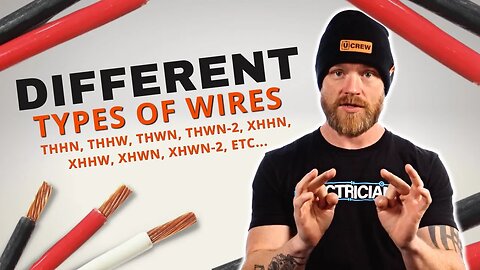
What's the Difference Between All These Wire Types?!?!
As with most things in the construction industry, there are multiple ways to perform every task and there are MANY different types of materials to use! The wire we use in the electrical field is no different. So, what are the differences in the types of wire and where can we use each? In the latest installment of Electrician U, Dustin brings to light (pun intended!!) some of the more common types of wire.
[00:26] - Intro
[02:00] - Sizing 310.15 (ampacity)
[02:50 - Steve "The Namer of Things"
[03:35] - 310.4 Table
[10:50] - Merch messages
[14:13] - Outro
🤘⚡️MEMBERSHIP⚡️🤘
JOIN ELECTRICIAN U - become a member and get:
FREE Continuing Education every year
FREE Practice Exams
FREE Monthly Video Courses
FREE Monthly Educational Newsletter
Premium Members-Only Content
Private Discord Channel
Monthly Members-Only Discord Chats
Sign up here --- https://www.electricianu.com/electrician-u-membership/
🎧🎹MUSIC AND VIDEO:🎹🎧
https://www.facebook.com/descantmv
🎬✍️ART AND ILLUSTRATION:✍️🎬
https://www.daverussoart.com
Article 310 of the NEC covers conductors for general wiring. Table 310.4(A) within the article covers conductors and insulations rated for 600v, and this is the table we would use for most of our general electrical applications. One thing to keep in mind here is that the tables in Article 310 are referring to the different INSULATION types as that is what is generally changing from one certain conductor to another. Not necessarily the metal within but the insulation.
Reading the tables are relatively easy. Left column is the trade name, second from left is the abbreviated version (what we would refer to the conductor as so we don’t have to say the entire thing each time!), third in the order is the temperature the conductor is good for, 4th is what environment the conductor can be used in, the 5th column is what the insulation is made of, the next three columns give you the insulations thickness and the last column lets us know what type of overall outer covering the conductor has.
The operating temperature column you see may have 2 different temperature ratings. This means the wire is rated for dual use. Look one column to the right and it will tell you what environment each temperature rating is good for. Also, there may be fine print notes next to an item, and to see what those are, just go to the end of the table and they are all listed there! These may contain conditions for the special applications or something of that nature.
Ok, so on to something we may see a bit more often. THHN is a conductor type that we use often. We can see that its insulation is of a thermoplastic nature (that is the T in the abbreviation), that the conductor is good for 90 degrees (that is the HH in the abbreviation), and that it has an outer covering of nylon (that is the N in the abbreviation). THHW is another conductor we may use often. Reading its information, we see that it is relatively the same as THHN, but it can be used in WET or DRY locations (that is the W in the abbreviation). THW is also close to the other two we just mentioned, but it is only allowed to be used as a 75-degree conductor (hence the single H). THWN is next on the list, and reading its composition, we can see that it still is a thermoplastic insulation type, rated for 75 degrees, moisture resistant, with an outer coating of nylon. THWN-2 is closely related but that 2 signifies that it can be used in a 90-degree environment as well. TW is the last of the thermoplastic conductors within the group. Much the same as the others, but without the heat ratings, it is only allowed to be used as a 60-degree conductor.
Thermoset is also something quite common for us electricians. The conductor types are preceded with the letter X. They are structured much the same, but have a thermoset type of insulation, whereas the others we discussed were of the thermoplastic type. Thermoplastic insulation types will break down and almost melt when heated too much and harden when cool. Thermoset insulation types are insoluble and non-melting.
So, picking the wire type to use isn’t terribly awful. You must research what environment you will be using the conductor in, what type of heat rating you want it to have, and a few other job specific items and there you have it!
#electrician #electrical #electricity
60
views
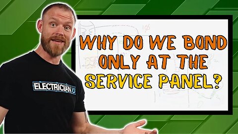
Why Do We Bond at the Service Panel and Not a Subpanel?
An important question was raised by one of our viewers. Why do we bond at the Service Panel and not at the Subpanels? A very valid and super important question that Dustin brings answers to in the latest episode of Electrician U.
CHAPTERS
[00:00] INTRO
[01:07] Merch messages
[01:42] Start of explanation
[03:58] Objectionable Current
[09:21] Example 2
[13:05] Example 3
[18:28] Bonding Wrap up
[19:07] OUTRO
🤘⚡️MEMBERSHIP⚡️🤘
JOIN ELECTRICIAN U - become a member and get:
FREE Continuing Education every year
FREE Practice Exams
FREE Monthly Video Courses
FREE Monthly Educational Newsletter
Premium Members-Only Content
Private Discord Channel
Monthly Members-Only Discord Chats
Sign up here --- https://www.electricianu.com/electrician-u-membership/
🎧🎹MUSIC AND VIDEO:🎹🎧
https://www.facebook.com/descantmv
🎬✍️ART AND ILLUSTRATION:✍️🎬
https://www.daverussoart.com
So, in a typical scenario, we would bring our ungrounded (hots), grounded (neutral) and grounding (ground) conductors into our service. This is at the point that we would bond the grounded and the grounding conductors together. From there, our all the conductors leave and can enter another panel where they are kept separated with no bonding. The primary reason for that grounding conductor is to set an alternate path back to the voltage’s source (breaker or fuse etc.) in case something happens, so there is another path back for the breaker to trip. Without that alternate path, the chances for someone to get shocked are considerably higher.
One of the reasons we separate the conductors past the Service Panel has to do with Objectionable Current. Simply stated, it is current that is going multiple directions at the same time; those directions we DON’T want it to go in! normally, that current leaves the source on the ungrounded wire, travels through the source, and returns to the source on either the grounded conductor or the other ungrounded conductor at the equipment. Objectionable current would be if a wire came off and touched something it wasn’t supposed to and sent the current somewhere else. The neutral conductor is expected to carry current; ground wires are not meant to carry them on anything other than a fault condition. If we didn’t bond the neutral and ground together at some point, we potentially could have objectionable current flowing on BOTH the neutral and ground at the same time and trying to return to source creating a considerable amount of havoc along the way!
If there was an event, say a ground fault where one of the ungrounded conductors touched the case of a dryer, the grounding conductor would carry that objectionable current, momentarily, back to the service panel, where it is bonded to the neutral, thereby completing the circuit. In fact, since the load itself was taken out of the equation (by touching the case and bypassing the load itself) the breaker sees SO MUCH current, that it does exactly what it is supposed to do and will trip. If that grounding wire was not there, and the complete circuit was not made, there would be potential for current to be on ALL the metal downstream from the service point and someone could get severely injured.
So, wouldn’t extra bonding be good by bonding in each panel location? If we were to bond in EVERY panel, then we would leave MULTIPLE paths that the current COULD take on its way back to source to complete the loop, and we would be defeating the purpose of trying to direct the current back to its source. In addition, if the neutral and ground were bonded in EVERY panel, then under the same circumstances, we would be sending potential to EVERYTHING plugged into ALL the circuits. So, we BOND it at the one spot only so we can keep the current corralled along the way WE want it to go and not energize everything along the way!
Please continue to follow Dustin and his travels here at Electrician U. Don’t forget to check in often as we are adding new items several times a week!
#electrician #electrical #electricity
94
views
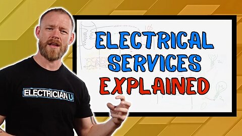
How Does an Electrical Service Work? Electrical Service Panels Explained
The term “Electrical Service” can be confusing for many electricians. What does it consist of? Why are there different sizes? Why do we have overhead and underground services? Where does the service start/stop and where does the building power take over? In the latest episode of Electrician U, Dustin answers several of these questions surrounding the topic.
🤘⚡️MEMBERSHIP⚡️🤘
JOIN ELECTRICIAN U - become a member and get:
FREE Continuing Education every year
FREE Practice Exams
FREE Monthly Video Courses
FREE Monthly Educational Newsletter
Premium Members-Only Content
Private Discord Channel
Monthly Members-Only Discord Chats
Sign up here --- https://www.electricianu.com/electrician-u-membership/
🎧🎹MUSIC AND VIDEO:🎹🎧
https://www.facebook.com/descantmv
🎬✍️ART AND ILLUSTRATION:✍️🎬
https://www.daverussoart.com
In the simplest terminology, the electrical service is the point at which power from the utility enters the residence/structure. Usually this takes the form of a utility transformer, which steps down the power to something we can use (say 120/208v or 277/480v). That transformer consists of a primary side (coming from the power generating station) and the secondary side (that which is at a much lower voltage) going to the building itself. As with all electrical circuits, each side of the transformer consists of a complete loop (or circuit) that allows the flow of electrons to return to its source. Different sizes of loads require different sizes of services. A house for example, since it is not large in size, will have a service from 125a to 200a, while a commercial building can have a service up in the thousands of amps depending on the size of the building and what’s being powered. Something to consider is the ground. Electrical services do not have a grounding conductor with them (normally). We derive the ground at the point of utilization. In other words, once the utility has brought power TO the structure, THEN we bond our neutral point to the earth so that a safe alternate grounding path is available for the circuit to return to its source and trip a breaker or blow a fuse. Most utility companies will disperse their power in three phase, dropping two of them off to be used at single phase installation (like a residence or smaller commercial space) and using all three phases at the larger commercial/industrial applications. Most residential power circuits do not require three phase to operate, so the utility doesn’t typically send three phase to residential neighborhoods. The commercial/industrial installations require three phase to be more efficient with all of the different items needed to make the building operate- lights, large and small motors, receptacles, equipment, etc.
When it comes to grounding the system, there are 3 basic items to remember. The Grounding Electrode is the item used to connect the system to Earth- like a ground rod, or grounding plate, or Ufer ground. The Grounding Electrode Conductor physically connects the Grounding Electrode to the system, usually in the form of a wire. Without it, the system would have no way of being connected to the earth. The Equipment Grounding Conductor is what we would normally associate with the ground wire connecting our electrical equipment together. It is meant to bond all of our equipment together and leave everything with a safe alternate path of grounding.
Overhead and underground services are available, and you will see both used frequently. While newer installations will put the service underground, the older ones you normally see overhead. Aesthetically, it is much more pleasing to the eye not having to see the overhead wires and poles, and technology/equipment have become much better in the recent era to allow us to dig them in. The meter itself is also considered part of the electrical service as this is where the utility can measure the amount of electricity being used and charge accordingly.
#electrician #electrical #electricity
0:00 Introduction
1:15 ELECTRICAL SERVICE
4:53 SINGLE PHASE & THREE PHASE
15:20 OVERHEAD / UNDERGROUND
19:13 DIFFERENT SIZES OF SERVICES
24:31 DIFFERENT WIRE AND RACEWAYS
166
views

How Should I Price Out Jobs? 5 Different Methods You Can Use to Estimate a Job!
How do you price out a job that you are going to do? Certainly, a valid question as we don’t like to take on work and lose money!! In this episode, Dustin dives into this topic to shed some light on the subject.
🤘⚡️MEMBERSHIP⚡️🤘
JOIN ELECTRICIAN U - become a member and get:
FREE Continuing Education every year
FREE Practice Exams
FREE Monthly Video Courses
FREE Live Instructor-Led Classes
FREE Monthly Educational Newsletter
Premium Members-Only Content
Private Discord Channel
Monthly Members-Only Discord Chats
Sign up here --- https://www.electricianu.com/electrician-u-membership/
🎧🎹MUSIC AND VIDEO:🎹🎧
https://www.facebook.com/descantmv
🎬✍️ART AND ILLUSTRATION:✍️🎬
https://www.daverussoart.com
02:28 - 1 Time and Material Method. This is a great one to use if you don’t know what exactly you are getting yourself into! If something starts off small but has the potential to grow into a huge project, or there is a ton of troubleshooting or remodeling are great examples. In a nutshell, you are charging for your time it took you to do the work and the materials. Maybe the time for you to go get the materials also. It keeps the person doing the work from losing money by giving a cost up front that was too little for the unseen items or too high of a price for the person having the work done by giving a price that tries to account for EVERYTHING that you COULD encounter.
04:51 - 2 Cost Plus Method. This simply is coming up with the cost you THINK it will take to do the project and then adding in what you need to make as profit. This is most often used when you know the hours and materials it will take to perform the work and then you add what you want to make on top of paying all of your bills etc.
3. Square Foot Pricing. While normally used for new construction, this method uses information taken over time from the AREA that the work is being done in. So, say new homes in Austin Tx, on average, are being built for X dollars per square foot, with the electrical portion of that work being Y dollars. Then you just use that number per square foot, multiplied by the square foot of the project you are going to be estimating!
4. Task Based Pricing. A good one to use when just starting out, you simply charge per the task you are going to be doing and then can adjust a LITTLE BIT for being job specific. So, let’s say you come up with $60 to hang a light fixture- that covers the cost of all of your expenses and the time it takes to hang the light. Then adjust a bit if you need a taller ladder or if you have to move a bunch of their items out of the way or things like that. It can be a quick way to give a price but requires history in knowing how much you have made over time doing those types of things to be the most profitable.
5. Estimating Software. There are several different products that are available from a multitude of suppliers. Usually, larger companies use this method as the costs to own or lease the software can be high, as well as those companies needing very specific margins to be the most efficient. Typically, these software programs allow you to input your hourly rate, up to date pricing for materials, and an hourly time frame to install something. So, if you were estimating a project that wants 12 receptacles- the program would assign maybe an hour and a half (or whatever you set it at) times 12, then add the materials to install them, add something for fuel, vehicle maintenance, overhead, profit, and then says it would cost $X. A great system to use if you want to be as accurate as possible!
A few things to keep in mind. First, trip charge. Your time shouldn’t be free. And if you are making multiple trips to a single place and not get the work in the long run, it could end up being a huge waste of money for you. The other thing to consider is minimum charges. What is the minimum amount of money you would be willing to make to show up and do work? If $50 was charged to just replace a switch, is it worth your time to do the running around, replace the switch, do the paperwork to get paid, etc.? More than likely a $150 minimum or $200 minimum would be better. If you only accepted the $50, all the time invested in making that $50 you would not be able to be somewhere else potentially making more money.
#electrician #electrical #electricity
111
views

Does Current Flow on the Neutral?
There are a lot of people out there discussing this whole neutral thing and it can be a little difficult to understand what is going on without being able to see what is happening.
🤘⚡️MEMBERSHIP⚡️🤘
JOIN ELECTRICIAN U - become a member and get:
FREE Continuing Education every year
FREE Practice Exams
FREE Monthly Video Courses
FREE Weekly Live Instructor-Led Classes
FREE Monthly Educational Newsletter
Premium Members-Only Content
Private Discord Channel
Monthly Members-Only Discord Chats
Sign up here --- https://www.electricianu.com/electrician-u-membership/
🎧🎹MUSIC AND VIDEO:🎹🎧
https://www.facebook.com/descantmv
🎬✍️ART AND ILLUSTRATION:✍️🎬
https://www.daverussoart.com
Let’s start this off by stating yes, current does flow in a neutral. But there are times when it doesn't. To understand this we need to look at exactly where in the circuit we’re examining. If we are near a device, somewhere in a branch circuit, there will most likely be current flowing at that point. If we look further forward in the circuit, to the electrical panel, this is where things get interesting.
If a panel is perfectly balanced, and we have 2 loads that we are looking at, then each of those branch circuits will have neutral current flowing throughout the entire branch(es). But the neutral from the electrical panel back up to the transformer, will not. When two loads are turned on, and are exactly the same, the neutral current can actually balance out and, in fact, cancel each other out.
Neutral conductors from a panel back to a source will carry any imbalanced current that exists between any two phases on the system.
#current #neutral #electricity
01:10 - Panel Drawing
03:50 - Conductor drawing
05:00 - Magnetic field examples
05:36 - moving on
06:00 - Example of current on a neutral
07:00 - Better analogy
07:57 - Why does current disappear?
10:00 - Field interaction cancellation
12:00 - Circuit Diagram view
15:00 - Math (Ohms Law)
18:25 - Jules law
20:40 - Bringing it all home.
69
views

Why Do YOU Think My Hot Tub Tripped?
In the latest episode of Electrician U, Dustin takes us on his trip to Breckenridge Colorado (well, a small portion of it anyways!!). See? We do more than just work here at Electrician U. well, sometimes!! Let’s dive in and see what he found out.
0:00 - The Problem
1:47 - Intro
2:00 - Merch messages
2:35 - CODE TIME
5:00 - Code violation???
6:50 - The BEARD
🤘⚡️MEMBERSHIP⚡️🤘
JOIN ELECTRICIAN U - become a member and get:
FREE Continuing Education every year
FREE Practice Exams
FREE Monthly Video Courses
FREE Weekly Live Instructor-Led Classes
FREE Monthly Educational Newsletter
Premium Members-Only Content
Private Discord Channel
Monthly Members-Only Discord Chats
Sign up here --- https://www.electricianu.com/electrician-u-membership/
🎧🎹MUSIC AND VIDEO:🎹🎧
https://www.facebook.com/descantmv
🎬✍️ART AND ILLUSTRATION:✍️🎬
https://www.daverussoart.com
In the cabin Dustin was staying in, there was a hot tub! I mean, why not right?! Well, upon trying to use said hot tub, Dustin encountered a problem where the hot tub quit working as he was toggling the buttons on the display. Why would this happen? The hot tub appeared to be all but brand new. Looking at the electrical panel, it was equipped with the required GFCI breakers feeding the hot tub like it is required to be. So, if nothing appeared to be damaged and everything seemed like it was wired appropriately, then why? Before we tend to that, lets dig into the code and see what we can find.
Article 430.6 of the NEC concerns ampacity and motor rating determination. Table 430.248 deals with full load current of single-phase AC motors (so we could check the amperage draw of the motors of our hot tub). Article 680 is all about swimming pools, fountains, and similar installations (which is the category that our hot tub would fall into) and will also have pertinent information about hot tubs.
Overall, there are a few general rules one should follow when doing a service type call on a situation like this. First thing would be to check the breaker. Did it trip and cut the power off to the equipment? Something to keep in mind when checking breakers is that the breaker handle may NOT always go to the middle (or tripped) position. Some breaker handles have a habit of barely moving, but still be tripped. It is best to actually put your hands on the handle itself and check. If the breaker did trip, the big question would be WHY? Usually, breakers do not just trip, there is almost always a reason why. Check the motor ratings in the above code article (add them together if there is more than one) and see if the breaker is capable of carrying the entire load. Remember to account for the heater also, as that would most assuredly add amperage to the circuit. Also check for loose wires within the junction boxes/panels as something may have come loose interrupting the circuit.
After some investigation, Dustin concluded that the breaker in fact did trip in the panel that was supplying power to the hot tub. There are 2 motors for the hot tub rated at 230v, 2.5hp each. Using the above-mentioned chart, he came up with 14.5a for each motor. Considering that adds up to 29a AND THEN adding the heater on top of that, the issue is most likely an overloaded circuit if both motors come on at the same time with the heater running as well!
What are your thoughts? Do you guys and gals have any ideas on why this particular hot tub would trip the breaker? Chime-in in the comments section and let’s see what we can come up with! Considering everyone viewing this has some experience in the electrical industry, if we were to add all of that together, someone is bound to have answers! Continue to watch Electrician U as we are constantly adding new content to the site! Also, did anyone happen to see who kept popping up in the window as Dustin was looking at the codebook? I wonder who that is??
#electrician #electrical #electricity
700
views
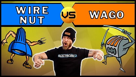
Should We Use WAGOS or WIRENUTS?!?!
In the latest segment of Electrician U, Dustin answers the question- Should we be using Wire Nuts or Wago’s out in the field to splice our wires? While the answer in your head should seem easy enough, there are several things to consider when choosing your wire splicing materials.
01:39 - Pre-twist gang
02:50 - CODE TIME
08:55 - Why I use what I use
🤘⚡️MEMBERSHIP⚡️🤘
JOIN ELECTRICIAN U - become a member and get:
FREE Continuing Education every year
FREE Practice Exams
FREE Monthly Video Courses
FREE Weekly Live Instructor-Led Classes
FREE Monthly Educational Newsletter
Premium Members-Only Content
Private Discord Channel
Monthly Members-Only Discord Chats
Sign up here --- https://www.electricianu.com/electrician-u-membership/
🎧🎹MUSIC AND VIDEO:🎹🎧
https://www.facebook.com/descantmv
🎬✍️ART AND ILLUSTRATION:✍️🎬
https://www.daverussoart.com
First, lets establish WHAT a Wago is. Just like almost everything else in the electrical industry, there are several terms for each material! Wire splicing components are no different. Wago is actually a brand name (one of the first to produce the product) of a push in type wire connector; whereas a wire nut requires twisting force to accomplish the connection. They both have metal connections within the wire splicing item to ensure continuity of the splice, but Wago type wire connectors are much more efficient as they do not require the electrician to twist the wires together with a tool before applying the connector (or using the connector to do the twisting) but the electrician simply pushes the wires into the connecting holes and the metal jaws do the rest of the work.
The NEC requires that things be installed per the manufacturer’s instructions. You can find the code reference in Article 110.3(B) of the NEC. In a nutshell, it states that if you do have a piece of equipment that is labeled, listed, or both that you SHALL install AND use per the instructions that are included in the labeling or listing. There are instances within the NEC that do require things to be listed, but this is an item-by-item requirement and should be researched for each task you are performing. Article 110.14 (Electrical Connections) governs wire splicing materials. In essence, it tells us that they wire connectors be identified for the material of the conductor (either copper or aluminum or both) AND shall be properly installed and used. So, having said all of that, as far as the NEC is concerned, if we are using a wire splicing method that is approved for what we are doing with it, identified for the materials being spliced, and installed per the manufacturer’s instructions, pressure type wire connectors are fine.
If the NEC is good with it, next would be installer preference. If it is an item that probably won’t be serviced or changed often (say a residential switch or receptacle) then wire nuts would be the way most of us would go. We would twist our wires together, install the device, and push it back in the box and leave it. There is really no need to get back into it unless something goes wrong, or the device wears out or something like that. If it is something that will most likely require replacement (such as the rows of fluorescent fixture ballasts in warehouses or large retail stores) then a Wago type wire connector may be more beneficial for us to use as we would not have to untwist each and every joint to replace the item.
Wire composition is another factor to consider. Most pressure type wire connectors do not do a great job on stranded conductors but are made more for solid wires. However, Wago DOES have some lever lock type push in wire connectors that will accept stranded wires. As with anything, do your research on what you are wanting to use to see all the different options available. Cost is also another thing to keep in mind when selecting wire connectors. Wago type wire connectors are usually much higher than standard wire nut type, although they have come down in price considerably over the past several years. Keep in mind that what you are paying for is efficiency, so the cost of the material may justify itself if it saves the installing electrician time in installing several of these.
#electrician #electrical #electricity
93
views
Do Different Voltages Mean the Same Thing?
Just as with the plethora of different materials in the electrical industry, have you ever wondered why we have so many voltages that can mean the same thing? It can be confusing at best! In the latest episode of Electrician U, Dustin answers this question to bring some clarity to the subject.
🤘⚡️MEMBERSHIP⚡️🤘
JOIN ELECTRICIAN U - become a member and get:
FREE Continuing Education every year
FREE Practice Exams
FREE Monthly Video Courses
FREE Weekly Live Instructor-Led Classes
FREE Monthly Educational Newsletter
Premium Members-Only Content
Private Discord Channel
Monthly Members-Only Discord Chats
Sign up here --- https://www.electricianu.com/electrician-u-membership/
🎧🎹MUSIC AND VIDEO:🎹🎧
https://www.facebook.com/descantmv
🎬✍️ART AND ILLUSTRATION:✍️🎬
https://www.daverussoart.com
Early on in its life in the US, electricity was run to our streetlights somewhere around 100v. As time went on, this was increased to about 110v to increase the amount of light. This was the norm until recently (say the last 50 or 60 years +/-), where for the same reasons, it again was increased to 120v and 240v where we now currently reside in the voltage scale. However, when we talk about voltage at any particular point, we are referring to NOMINAL voltage, or in other words- Close to. A small percentage (up or down) will typically be acceptable in most instances. For our standard voltage of 120v, generally anywhere between 114v to 126v is common.
Now, you may notice that on some materials, say a light bulb for example, it will be stamped on it with its wattage along with 130v. This means that the lamp is RATED for voltages as high as 130v to handle the fluctuation of voltage throughout the day. Also, notice how on some devices like receptacles, it is labeled as 125v 20a or 125/250v 30a. All this means is that the device in question is rated for that many amps of current at the voltage range listed (usually a bit higher on the scale than normal). Remember from previous episodes, voltage and amperage are proportional to one another. Raise one and the other will also go up. So, if we were to raise the voltage above 120v, the amperage associated with it would also go up. So, they rate the devices at the amperage you are wanting to use at the higher end of the voltage available to have a bit of a safety buffer in there. If that were not to be the case, if your voltage went up, then your device rating (amperage wise) could potentially be exceeded, and a fire hazard could be present.
Another item to look for is dual voltage ratings on a device. Most of our dryer and range receptacles, for example, are rated either 30a or 50a at 125/250v. This simply means that the device is rated to carry the amperage it is stamped with at either 125v or 250v. It is manufactured to work at either voltage, but the equipment you are plugging into it may not be, so make sure to check the equipment requirements/ratings!
Motors on the other hand tend to be on the inverse of this scale. You typically see 230/460 which is on the lower end of the standard voltage scale of 240v or 480v. Knowing that voltages vary depending on load, the manufacturers rate their motors on the low scale to let us know that this is the lowest amount of voltage that should be applied to their motor so it can operate without damage. In any given facility, the more you have operating at once, the lower the voltage typically is overall, so the equipment manufacturers see LOWER voltages as more common than high. Now, damage can also happen by applying to HIGH of a voltage, but the manufacturers deem it more advantageous to label it with the low end of the voltage spectrum than the upper end. Again, check the equipment requirements/ratings before applying voltage to it!
We hope you learned something by watching the video. Continue to look frequently at the site as new videos and content are being added all the time!
#electrician #electrical #electricity
2:00 - Example 1
2:57 - Utility voltage
4:12 - Plug Examples
50
views

Kitchen Remodel - At Parents House
Here at Electrician U, we don’t like to sit around stagnant. Oftentimes, we head out into the field to perform work or to explain skills or questions. In this episode, Dustin takes to the road and heads to Minnesota so he can assist in his parents kitchen & home remodel. Even helping out the folks can lead to a teaching moment!
🤘⚡️MEMBERSHIP⚡️🤘
JOIN ELECTRICIAN U - become a member and get:
FREE Continuing Education every year
FREE Practice Exams
FREE Monthly Video Courses
FREE Weekly Live Instructor-Led Classes
FREE Monthly Educational Newsletter
Premium Members-Only Content
Private Discord Channel
Monthly Members-Only Discord Chats
Sign up here --- https://www.electricianu.com/electrician-u-membership/
🎧🎹MUSIC AND VIDEO:🎹🎧
https://www.facebook.com/descantmv
🎬✍️ART AND ILLUSTRATION:✍️🎬
https://www.daverussoart.com
Before diving into this video, make sure to recognize that you may be working with live wires until you can prove what goes to what. If you are comfortable with and have proven experience, you can leave things energized as this can make things a bit easier to trace out. BUT, only if you have experience. An inexperienced electrician should NOT work things energized! Get assistance if needed from someone who understands!!
One of the things you can do to help you assist yourself in any remodel situation, is to leave as much put together as you can until you can figure out what goes to what, what is needed, and what needs to be removed or reworked. If you dive right in there and just start ripping things out without doing the research, it will usually result in some serious head scratching and/or doing unnecessary rework. Another item to reconsider is minimizing the amount of drywall or finishes you will need to disrupt to install your new work. It may seem easier to just start slashing at the drywall, but in the long run, you can make it easier for everyone involved and have a much happier customer if you spend a bit of time planning for the least amount of damage. If you leave a customer feeling good about the services you provide, they are much more apt to contact you for future work, which is one of the goals of working for yourself!
Another item you can do to save yourself some hassle in figuring out what is what is to label things as you figure out where they come from and where they go. You can write on the conduit/nonmetallic cable itself as well as make yourself a paper (or electronic) diagram. This will help you keep track of things as well as anyone else involved in the project. This is no different really than keeping as built drawings on our larger commercial projects we do.
Something else to keep in mind when digging into remodel work is that there have probably been several different people in that place working over many many years time, some of them who are probably not qualified to do so! You will come across installed items that are no longer code compliant, and some items that never would have been. Point is, just because we may find something inappropriate, it doesn’t give us license to continue to do it! If you find a problem, as a professional, it is part of our responsibility to correct the issue and notify the homeowner of the situation. If its something small, it may not result in a charge. But if it is fairly large issue, you can charge for it, but it still needs to be corrected.
Once things have been sorted out as to what is staying and going, the new added items will be installed. This can be new fixtures, switches, or receptacles. Match heights of existing switches and receptacles so things don’t necessarily look like it’s a new item. After everything has been added and roughed in, its time to trim out and install the finished devices and trim. Make sure to install the plates to the switches and receptacles if the house or project will be occupied. We certainly do NOT need to have our clients get a wicked nasty shock!
Remember, install your work in a clean professional manner, safely and correctly! If you are watching these videos, then you definitely know how to do it right!
#electrician #electrical #electricity
01:30 - My thoughts on solving the mess.
03:22 - Label label label
05:00 - Crazyness
07:20 - Sorry mom
42
views

Ohms Law - Directly vs Inversely Proportional - For Electricians
Ohm’s Law. Something that us electricians use on almost a daily basis to perform our tasks. But that doesn’t mean that it is all easily understood. In this latest episode, Dustin again answers our viewers questions regarding this and sheds some light on the subject.
🤘⚡️MEMBERSHIP⚡️🤘
JOIN ELECTRICIAN U - become a member and get:
FREE Continuing Education every year
FREE Practice Exams
FREE Monthly Video Courses
FREE Weekly Live Instructor-Led Classes
FREE Monthly Educational Newsletter
Premium Members-Only Content
Private Discord Channel
Monthly Members-Only Discord Chats
Sign up here --- https://www.electricianu.com/electrician-u-membership/
🎧🎹MUSIC AND VIDEO:🎹🎧
https://www.facebook.com/descantmv
🎬✍️ART AND ILLUSTRATION:✍️🎬
https://www.daverussoart.com
The question came from the viewer as- Voltage and Amperage Directly Proportional to each other and Resistance is Indirectly Proportional to Current. So how exactly does that all work together?
Well, Directly Proportional means that if you were to raise one value, the other directly proportional item would also go up. Indirectly Proportional means that if you were to raise one value, the indirectly proportional item would go down. Voltage and amperage are directly proportional to each other, so if you were to raise the value of the voltage, the amperage would also go up.
Dustin also does a good job of explaining how to use the 3 value Ohm’s Wheel (Volts, Amps & Resistance). If you draw the wheel with the Volts on top, Amps on the bottom left, and Resistance on the bottom right, all you have to do is cover up the value of the one you are trying to find and perform the equation with what’s left. So, if you were looking for Amps you would need to divide Voltage by Resistance (I=E/R). If you were looking for Resistance you would divide Voltage by Amps (R= E/I).
For example, if you had something that was being powered by 120v and the item had 10 Ohms of resistance, that would result in that item drawing 12a worth of current. We can check the proportionality of the two by raising one of the values and recalculating. So, say we changed the voltage to 240v and kept the 10 Ohms worth of resistance, we can see that amperage changes to 24a. This means that Amperage and Voltage are directly proportional. Change one either up or down, and the other changes up or down with it.
Let’s check the indirect proportionality of Resistance and Current. If we had something operating at 240v and was drawing 5a worth of current the Resistance would be 48 Ohms. If we were to change the current to 15a and leave the voltage at 240v, the result would be 16 Ohms of resistance. This tells us that Current and Resistance are Indirectly Proportional to one another. If you raise one up or down, the other does the opposite of what you did with the first value.
Please continue to follow Dustin Stelzer and Electrician U! Also, don’t forget to send in your questions so Dustin can get you the answers you are looking for!
0:51 - Ohms law
1:24 - Examples Break Down
2:40 - Resistance example
5:28 - Inversely proportional example
#electrician #electrical #electricity
73
views
Why Do Outlets Have Different Types of Holes?
As electricians, we are called upon to install (among other things) many different types of receptacles to give our clients something to plug their equipment into. But why do the receptacles look so different from one another. In the latest episode of Electrician U, Dustin dives into this topic to give our followers answers to their questions.
🤘⚡️MEMBERSHIP⚡️🤘
JOIN ELECTRICIAN U - become a member and get:
FREE Continuing Education every year
FREE Practice Exams
FREE Monthly Video Courses
FREE Weekly Live Instructor-Led Classes
FREE Monthly Educational Newsletter
Premium Members-Only Content
Private Discord Channel
Monthly Members-Only Discord Chats
Sign up here --- https://www.electricianu.com/electrician-u-membership/
🎧🎹MUSIC AND VIDEO:🎹🎧
https://www.facebook.com/descantmv
🎬✍️ART AND ILLUSTRATION:✍️🎬
https://www.daverussoart.com
Let’s start with the standard 120v receptacle. A standard 15a receptacle has 2 vertical slots (one each for the hot and neutral) and a dome-shaped for the ground, while the 20a receptacle looks almost identical but the neutral slot also has a horizontal opening. The reasoning is rather simple. If you had a piece of equipment that draws 15 amps, you can plug it into either a 15a or a 20a receptacle, as the receptacle is rated for it. If you had a piece of equipment that draws 20a, you can only plug it into a device rated for 20a otherwise it could potentially melt, as it draws a higher amperage than the device is good, for and start a fire. Something to consider, especially in the fall/winter months, is to be mindful of plugging in smaller temporary space heaters and overloading your circuitry. If you have a string of 15a devices wired to 20a breakers, its very easy to exceed the receptacles ratings and run the risk of a fire.
Another question is why are some of the slots on a receptacle larger than the others? If you are looking at the face of a standard 15a receptacle, you will immediately see that the left (neutral) slot is a bit larger than the right (hot). This is done so that you only plug the cord in, as intended, and provide whatever you are plugging in the proper polarity to each pole. In other words, it is meant for you to plug your equipment neutral into the neutral slot and the hot into the hot slot. By the neutral slot being bigger, it simply will not fit into the smaller hot slot. If the equipment is not affected by polarity or has a ground prong (so it can only be plugged in one way) the blades will be the same.
A single (or simplex receptacle) has only 1 spot to plug something into it. This would be for something that draws close to the circuit’s ampacity (like a chest freezer for example) or maybe something that you don’t want to share circuitry with (like sensitive electronics). A duplex receptacle, however, is the standard receptacle we see and use for most applications. This device has 2 places to plug into on the same yoke. If you were to place 2 duplex receptacles in the same box, you would consider that a quad, and would have 4 places to plug something into.
Device shape is also something to consider when installing receptacles. Standard or Decora? Standard receptacles are the normal ones we are used to seeing where the face of the receptacle takes on a rounder appearance with each place to plug into looking individual, while the Decora type receptacles are a single looking device with a pronounced square shape. Decora type devices not only look a bit nicer, but they also carry the added benefit of having the same type of plate for ALL the Decora switches, receptacles, GFCI’s, Etc.
The last part for Dustin to dive into is the 250v type receptacles. These would be the larger receptacles you would find in your home for the dryer or range (among others, but those being most common). They look considerably larger as they are rated to carry more amperage and voltage than our standard receptacles, but they are constructed similar, in that they have different slots that do not allow you to plug something into a device that it isn’t rated for.
#electrician #electrical #electricity
0:51 - Examples of Receptacle's
2:28 - Chord examples - Polarity
3:43 - Receptacle types
4:40 - 250 V Receptacles
6:30 NEMA Plug Diagram
55
views
Tips on Turning Side Work into a Business
00:00 Intro
00:26 Advise on starting a business
01:46 Having a shop on your property
02:31 Work Truck
04:00 Word of mouth
05:02 Billing and Accounting
05:17 Budgeting
06:09 Outro
At what point do you stop working for someone else and take the leap and start your own business? At some point or another, every businessman and businesswoman ask themselves this question. As a successful business owner himself, Dustin with Electrician U provides some insight into this topic.
🤘⚡️MEMBERSHIP⚡️🤘
JOIN ELECTRICIAN U - become a member and get:
FREE Continuing Education every year
FREE Practice Exams
FREE Monthly Video Courses
FREE Weekly Live Instructor-Led Classes
FREE Monthly Educational Newsletter
Premium Members-Only Content
Private Discord Channel
Monthly Members-Only Discord Chats
Sign up here --- https://www.electricianu.com/electrician-u-membership/
🎧🎹MUSIC AND VIDEO:🎹🎧
https://www.facebook.com/descantmv
🎬✍️ART AND ILLUSTRATION:✍️🎬
https://www.daverussoart.com
The very first thing you will need is a license! If you are considering owning an electrical business, then a master electrician license is what you should have. Some areas may also require you to have a business license or something similar, but at a minimum a master electrician license is required. If you perform electrical contracting work without a license, you will get into a pretty good amount of trouble, and you DO NOT want to start your journey behind the 8 ball!!
Next, you would have to either clear it with your current employer and make sure they are ok with you doing it as you usually would start off slow, on nights and weekends, and your employer may take offense to your being a competitor. Not to say that all employers are like that; some are quite ok with their employees rising through the ranks into entrepreneurship, but some are not. Approach them with the idea that you are not stealing their customers (or employees!) or undermine the company or anything sinister, you simply are looking to better yourself and step out on your own! Heck, they may even be willing to give you some tips and lessons that they learned along the way. You never know until you ask, but just make sure everything with your current boss is on the up and up.
A place to work out of is also definitely important as you will have tools, materials, and all the items you will need to use to be a successful business owner. But, when starting out, this can be in your garage, shed in the backyard, sometimes even the pickup truck is what you have access to and will use. As you become more and more successful in business, you will eventually grow out of the garage, but initially save the money for something that needs a financial solution.
Speaking of a place to work, you are going to need some type of vehicle to get from your shop to the jobsite to do the work, to the supply houses to get your materials, and even a way to get to the places to BID the work you are intent on doing! A pickup truck or van are usually the go to choices for contractors. However, you don’t want to run out and BUY a brand-new truck/van, but rather wait until you have enough revenue rolling in to justify the purchase. Use what you have when you are first starting out until you can prove that you can do the work, bid the work properly, go through both highs and lows (on the financial end), and that you have enough work on the horizon to be reasonably comfortable.
When considering the type of debts that we all must face, try to stay away from the consumer type debt (buying things out of want as opposed to out of need) and think about purchases that will result in a debt you could leverage and make work for you. Dustin tells the example of a bucket truck for work. Yes, it is an expense, but making that purchase would open up a considerably larger quantity of additional work you could do. Makes sense, but do not make those purchases initially but rather after you are on your way to success.
Billing and accounting when you are first starting out should be simple. Make yourself a budget and stick to it. There are tons of different software’s available, but something like Excel or a spreadsheet can work reasonably well at the beginning. You just must have a way to track your expenses, billings, etc.
69
views

Why We Bond Metal Boxes? Do Plastic Boxes Need Bonding?
As we are learning to install a quality electrical product during our apprenticeships, we are constantly reminded to bond our metallic boxes. But why do we bond metal boxes, and why DON'T we bond plastic boxes? In a never ending pursuit to answer his followers questions, Dustin once again provides a great explanation to this topic!
01:07 - CODE TIME
01:21 - Article 250 . 4a
07:45 - Why we land a ground
08:20 - Examples of a completed circuit
12:20 - Another Example
14:35 - Merch messages
🤘⚡️MEMBERSHIP⚡️🤘
JOIN ELECTRICIAN U - become a member and get:
FREE Continuing Education every year
FREE Practice Exams
FREE Monthly Video Courses
FREE Weekly Live Instructor-Led Classes
FREE Monthly Educational Newsletter
Premium Members-Only Content
Private Discord Channel
Monthly Members-Only Discord Chats
Sign up here --- https://www.electricianu.com/electrician-u-membership/
🎧🎹MUSIC AND VIDEO:🎹🎧
https://www.facebook.com/descantmv
🎬✍️ART AND ILLUSTRATION:✍️🎬
https://www.daverussoart.com
So why would we even bother to bond our metallic boxes if we aren’t required to bond our plastic boxes? To find the answer lets dig into our 2020 NEC and see what it has to say about the topic!
Article 250.4 (A)(3) Bonding of Electrical Equipment, of the 2020 NEC tells us that any normally non-current carrying (something that is normally not energized) conductive materials (metal for example) enclosing electrical conductors or equipment (conduit and boxes for example) shall be (must be) connected together (bonded) and to the electrical supply source.
What is an effective ground-fault current path you may ask? Article 100 of our 2020 NEC states that an Effective Ground-Fault Current Path is “An intentionally constructed, low-impedance electrically conductive path designed and intended to carry current under ground-fault conditions from the point of a ground fault on a wiring system to the electrical supply source and that facilitates the operation of the overcurrent protective device or ground-fault detectors”. This definition tells us that an effective ground-fault current path is a purposely constructed path that is meant to carry current under abnormal conditions (one that it isn’t normally supposed to) from the point of the fault to the source (a breaker for example) that lets the overcurrent protective device or ground fault detector to do its job (trip the breaker or blow the fuse).
So, in layman’s terms, we have to bond any metal conduit or boxes surrounding our wires together, so that in the event that something goes wrong, the offending electrical charge can be sent back to its source and allow the device protecting the installation to do its job. There could be any number of items that could cause a fault; terminations could come loose or break, things overheat, conductors burn up or go bad, or a myriad of other potential problems. Keep in mind that problems do not arise in the middle of a perfectly good installation, but rather at the termination or weak points (scuffs in the wire for example or points of corrosion).
Now that we have established that the NEC requires us to bond together our metal parts, let us dig a bit deeper still into things. Wouldn’t the ground be considered a redundant neutral? Absolutely not! The neutral is meant to have current on it returning to the source from the load allowing the circuit to create a full loop and work as it is supposed to. The ground path is an alternative path that still allows the objectionable current to return to its source under other than normal conditions. So, by bonding all of our metal parts together, it places them all on the same equal plane as a return path to the source of power giving the offending electricity a nice, easy, and quick path to return and trip the breaker or blow the fuse.
Thus far, we have established that we must bond our metallic materials together, which works fine for most of our commercial installations, but what about a residential installation or any installation where we don’t use metal (PVC for example)? Well, the code reference we gave earlier, says CONDUCTIVE MATERIALS must be bonded. So plastic (a non-conductive material) isn’t required to be bonded as it doesn’t conduct. Same rules would apply to PVC conduit.
#electrician #electrical #electricity
122
views

Final Studio Update - Behind the Scenes at the Electrician U Studio!!!
Filming and getting all the content ready for our follower’s consumption takes much more than just a video camera and a laptop. Much much more!! In the latest episode from Dustin, he gives a sneak peek into the new production space for Electrician U. There is so much that goes into filming the video episodes that the viewer does NOT see that this is a rare, interesting view of some of the things required to produce quality instructional videos. Dustin discusses the multiple camera/microphone setups, the new digital smart whiteboard, computer monitors, servers and even the soundproofing for the room
00:34 - INTRO
02:43 - The Rig
04:39 - Experiment wall
08:00 - Camera gear/ Drone
09:30 - JOSH
10:00 - The Office
10:37 - Material Wall
11:00 - Merch Area
🤘⚡️MEMBERSHIP⚡️🤘
JOIN ELECTRICIAN U - become a member and get:
FREE Continuing Education every year
FREE Practice Exams
FREE Monthly Video Courses
FREE Weekly Live Instructor-Led Classes
FREE Monthly Educational Newsletter
Premium Members-Only Content
Private Discord Channel
Monthly Members-Only Discord Chats
Sign up here --- https://www.electricianu.com/electrician-u-membership/
🎧🎹MUSIC AND VIDEO:🎹🎧
https://www.facebook.com/descantmv
🎬✍️ART AND ILLUSTRATION:✍️🎬
https://www.daverussoart.com
One of the favorite features of all of us is the new smart white board. This piece of equipment allows us to convey, via written word, the subject matter to our viewers. In this way, it is much like a traditional whiteboard. However, the new and improved version is digital, allows an almost endless range of colors, fonts, symbols, and other features, plus the ability to put pictures and documents on it so everyone can see makes this tool super versatile! And as soon as you are finished you can simply erase with the click of a button and start the next topic. One of these boards would make a schoolteacher green with envy!
No video production would be complete without a strong server & computer setup to save, edit and distribute the content, and ours is no different! Dustin had someone build a new state of the art computer to not only save all the video and audio content he creates, but it also immediately sends it to the audio/video editors in Massachusetts so they can begin tweaking and streamlining the information. By doing it this way, it not only saves a massive amount of time having to do things manually but is much more efficient and economical as well.
Included on the tour of the new facility is the instructional workshop area. This space was built around a stud wall to be able to show how to install NM cable/boxes, provide the wiring make up within them, electrical panel wiring, relay wiring, etc. We were able to fit a considerable amount of training/instructional options within a small space while keeping things looking new and presentable. Dustin even included a personal look at his artwork that he has done. Pretty impressive to say the least!
When it comes to the cameras, Dustin digs in deep to show the different models and accessories he uses. There are many different cameras that do several different things depending on the situation. Also included in the video portion is the lighting required to make the videos visually pleasing. It honestly looks much like a Hollywood movie set in there! And when the video production needs to go out into the field or away from home base, we even show off the different travel/storage options, from backpacks (several of them!) to hard sided cases, and audio equipment cases.
The last part of the walk through features the upcoming contracting side of the business. Storage area for tools, materials and office staff workstations are all present in a fashion that makes sense if you were to have a contracting business. As a good business manager would recognize, Dustin has decided to put a hold on this end currently so neither the contracting end nor the Electrician U end would suffer from lack of attention. A difficult decision at best, but definitely the correct one to make. Looking forward to the upcoming addition to the platform soon!
Here at Electrician U, we want to design, develop, film, and produce the highest quality educational content possible, and I think the steps Dustin has taken over the recent months certainly allows that to happen!
#electrician #electrical #electricity
50
views

"Best Gifts for Electricians" - Amazon Tool Review
While Dustin and the rest of us here at Electrician U tend to work very hard at coming up with interesting topics and producing quality videos and instruction, sometimes we just get a bit silly and need to blow off a little steam! In this episode, our video editor Drake from Descant Music and Video sent Dustin a “care package” of “best gifts for electricians”, didn’t tell him what was coming, and had him open the packages while on camera. Very entertaining to say the least!
00:30 - Intro
00:45 - Opening
01:20 - The Pen
02:37 - The Socket
04:34 - Magnetic Write Band
05:40 - The Gloves
07:40 - Multi purpose laser level
09:50 - Wallet multi tool
10:25 - The hammer
11:35 Merch Messages
🤘⚡️MEMBERSHIP⚡️🤘
JOIN ELECTRICIAN U - become a member and get:
FREE Continuing Education every year
FREE Practice Exams
FREE Monthly Video Courses
FREE Monthly Educational News Letter
Premium Members-Only Content
Private Discord Channel
Monthly Members-Only Discord Chats
Sign up here --- https://www.electricianu.com/
✍️👨🎓LIVE CLASSES👨🎓✍️
https://www.electricianu.com/live-online-electrical-classes/
👾🤖PRACTICE EXAMS🤖👾
https://electricianu.com/electrician-practice-exams-national-electrical-code/
😎👕MERCH👕😎
https://electricianu.com/eu-merch/
📲👥SOCIALS👥📲
Instagram - https://www.instagram.com/electrician_u
Discord - https://discord.gg/electricianu
Facebook Page - https://www.facebook.com/theelectricianu
Facebook Group - https://bit.ly/2tz7eQh
TikTok - https://www.tiktok.com/?electricianu
Reddit- https://www.reddit.com/r/ElectricianU/
Twitter - https://www.twitter.com/electrician_u
LinkedIn - https://linkedin.com/company/electricianu
🎧🎹MUSIC AND VIDEO:🎹🎧
https://www.facebook.com/descantmv
🎬✍️ART AND ILLUSTRATION:✍️🎬
https://www.daverussoart.com
First on the unveiling, a multi-tool pen set, which seems like it would be a very practical and useful gift for any tradesman or woman! Complete with pen/pencil, LED flashlight, super small Phillips and straight blade screwdriver, ruler, stylus, and a level one would think it has appeal to the tradesperson, so Dustin rates it a 6 on a scale of 1-10 as it is a bit hokey, and most electricians would already have most of these items on their person daily anyway.
Next up, a multi socket that will cover many different sizes without having to change from one size to the next. While good in theory as you wouldn’t have to carry your entire socket set to the work area, Dustin is gracious in his -9.6 rating as it didn’t drive the smaller headed screws very well and the thing started falling apart about 20 seconds into the test on literally the second screw! I would NOT spend the money on this tool- Epic Fail.A magnetic wristband is the next item to be tested. The wristband wraps around your wrist and has several strips of magnets that can hold your fasteners ON your wrist, without having to hold them IN your hand, freeing that up to steady your work. Dustin gives it an 8 out of 10 as it does in fact seem very useful in theory and the magnets are super strong. My favorite- LED outdoor gloves! Poor light placement, poor battery/switch location, and the fact that they are not really even gloves at all gives this tool a rating of -13.73542! While they do light up a darkened work area, they just are not practical in any way, offer zero protection, and are a Gimmick!! Save your money folks. Next thing to run the gauntlet, is a multi-purpose laser level. There are several good levels available on the market these days from manufacturers like Klein, Bosch, and Milwaukee so this thing has some big shoes to fill if it is going to be able to stand up against the others. Not to mention, after the last failure in the LED gloves, we need something good to carry us along! At first glance, it looks like it would be a perfect tool for someone who is into multi-purpose gadgets and not any self-respecting tradesperson, and after the testing, you would be correct in that assumption. The tool is not of quality craftsmanship, the tape measure will not stand out past a couple feet, nor will it retract without having to force it back in by hand. A 1.5 is all that Dustin is willing to rate the tool (which is a vast improvement from the last tool!) and would not suggest this as a companion to your other tools in your tool bag. A flat multi-tool that you could carry in your pocket or wallet is the next item to be tested. It has several different tools that you could potentially use- box/letter opener, ruler, cell phone stand, nut sizer, bottle opener, and several others that I am not sure what they could be used for. What it's NOT labeled on the list of usefulness of this tool is as a Throwing Knife! So, if you are out there somewhere in the world and in need of some protection, you could always throw the tool you have in your pocket at your attackers and perhaps make enough of a distraction to escape?
#electrician #electrical #electricity
144
views
Techniques on Stripping Wire - Awesome Tools to Help Electricians
Have you ever wondered "What is the correct way to strip wire?" With so many options of tools available on the market today to cover this task, in addition to the multitude of different techniques to use, the options are almost endless! In this episode, Dustin explores several hand wire strippers as well as discussing proper techniques to make the task much easier for an electrician to understand.
00:11 - Intro
01:45 - For #8 wire
01:57 - Klein Curve HD
02:30 - Klein Needle Nose Combination pliers
02:38 - Milwaukee Stripping Pliers
03:20 - Example of use
03:40 - The Angle approach
05:17 - The Left handed assist
06:23 - The way I bend hooks
07:55 - The Milwaukee M18 Stripper
09:20 - Stripping large conductors by hand
10:05 - Use of the M18 Stripper
12:10 - Sponsor message
12:30 - The End.
🤘⚡️MEMBERSHIP⚡️🤘
JOIN ELECTRICIAN U - become a member and get:
FREE Continuing Education every year
FREE Practice Exams
FREE Monthly Video Courses
FREE Monthly Educational News Letter
Premium Members-Only Content
Private Discord Channel
Monthly Members-Only Discord Chats
Sign up here --- https://www.electricianu.com/
✍️👨🎓LIVE CLASSES👨🎓✍️
https://www.electricianu.com/live-online-electrical-classes/
👾🤖PRACTICE EXAMS🤖👾
https://electricianu.com/electrician-practice-exams-national-electrical-code/
😎👕MERCH👕😎
https://electricianu.com/eu-merch/
📲👥SOCIALS👥📲
Instagram - https://www.instagram.com/electrician_u
Discord - https://discord.gg/electricianu
Facebook Page - https://www.facebook.com/theelectricianu
Facebook Group - https://bit.ly/2tz7eQh
TikTok - https://www.tiktok.com/?electricianu
Reddit- https://www.reddit.com/r/ElectricianU/
Twitter - https://www.twitter.com/electrician_u
LinkedIn - https://linkedin.com/company/electricianu
🎧🎹MUSIC AND VIDEO:🎹🎧
https://www.facebook.com/descantmv
🎬✍️ART AND ILLUSTRATION:✍️🎬
https://www.daverussoart.com
SPONSOR: https://www.milwaukeetool.com/Grid
With hand powered wire strippers being one of the more common tools us electricians carry and use on a daily basis, it makes sense to pick one that suits the individual's style, size, etc. A smaller pair tends to be a bit more nimble, but larger pairs tend to have more options and range of wire sizes. Ergonomics should also come into play when making your choice, as the average electrician will spend a vast amount of time stripping and making up wires. A small ergonomic pair of strippers ranging from 8-16 solid and 10-18 stranded that also have the capability to cut and thread 6-32 & 8-32 screws (as sometimes the screws to attach the device to the box are too long) are the best. As far as additional options, try some out to see if any are useful to you. Some are available with crimpers, some have built in reamers on the nose to ream smaller sizes of EMT, as well as needle-nose pliers with stripping holes in the jaws. There are even Hybrid pliers that combine the best parts of strippers, needle-nose and lineman type pliers into one tool!
In regards to technique, if you can remember and practice a few simple rules of thumb, you will master the art of wire stripping relatively quickly and easily! First, tilt your strippers toward you BEFORE you bite down on the insulation. THEN, while still biting down on the insulation, tip your strippers away from you creating a small gap in the insulation. Now, just use your thumb or finger to push the strippers away from you off the end of the wire! Done! Also, make sure to use the wire bending loop/hole on the strippers themselves and use your other hand to hold onto the wire being looped. This will result in a much cleaner and tighter loop that you can install around the screw of your device.
As with many tools in today's market, wire stripping has become something that you can do with a power tool. This powered option makes the process of stripping larger feeder type cables much quicker, easier, consistent and efficient. The Milwaukee 18v cordless wire stripper that Dustin tests here is capable of stripping 1/0 to 500 KCMIL and has a manual depth adjustment to set your strip length for up to 3 inches. This tool is awesome and will make the chore of stripping and installing feeder wires almost enjoyable!
If all else fails, you can just revert to the old school ways of doing things and use your razor knife to strip the cable. A couple simple ways of doing this. You can strip off a linear slice down the cable at the length you desire (making sure not to dig into the copper conductor), then run your knife around the cable (again ensuring you do not dig into the copper conductor) and pull off the insulation. Another variant of this would be to ring your knife around the conductor first, THEN slice horizontally. Either option has been the way we have stripped cable for years and continue to do so to this day!
#electrician #electrical #electricity
1.09K
views